
Posted on: 22nd July 2016 by Vicente Martin
As many of you may know, we have developed a suite of process models for the aluminium rolling industry. These aluminium rolling models cover everything from ingot pre-heating to tension levelling. Over the next few weeks we will be posting a series of Insights which demonstrate the practical application of our aluminium rolling models. We’ll also show you how easy they are to use.
First up is the Innoval Rolling Model. I’m going to explain how it can be used to determine the ground camber of work rolls.
A new business opportunity
In this particular case we’re going to take the example of a cold mill that mainly produces soft alloys like AA1050. The Marketing department of this company identified a business opportunity; manufacturing AA5052 for industrial applications.
The Process Engineering team has already evaluated that the mill is capable, in terms of power and load, to achieve the desired reductions, so they’ve planned a trial. However, the Production Manager is worried about the conditions of this trial, and particularly about flatness. Will the current roll crown be enough to accommodate the change in load? This is where one of our aluminium rolling models comes in.
Setting up the model
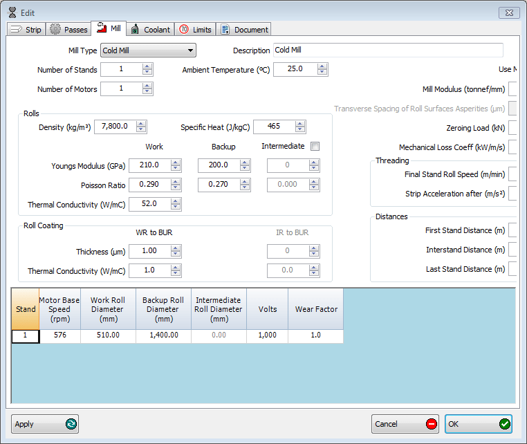
First of all, using the Innoval Rolling Model, we define the basic configuration of the mill. That’s the dimensions, geometry, power, lubrication and cooling, etc. This creates a ‘virtual mill’ for us to calculate any particular pass we need.
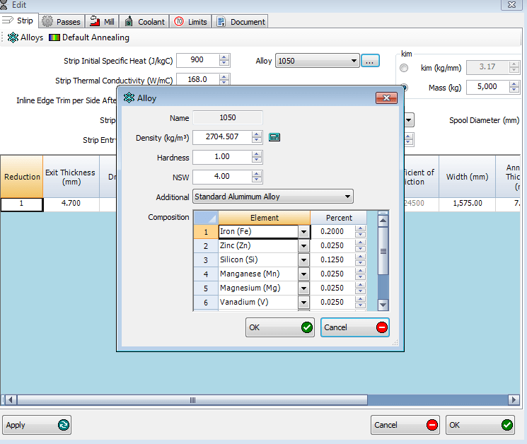
Once we have the mill set up, we can generate our simulated pass. To do this we select the material we’d like to roll. In this case it’s AA1050. It’s possible to select any AA alloy from a drop down list. Alternatively, we can use the actual composition to tune the stress strain behaviour of the material. This, together with information about the pass (speeds, tensions, anneals, etc.), means we are ready to generate a result for the steady state behaviour of this mill.
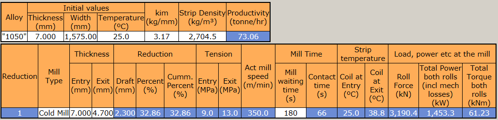
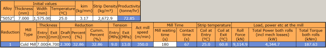
The rolling model calculates that our mill uses a rolling force of 3190 kN to roll this pass. Thankfully this matches the result we get in reality, otherwise a calibration would be needed.
Rolling the new product
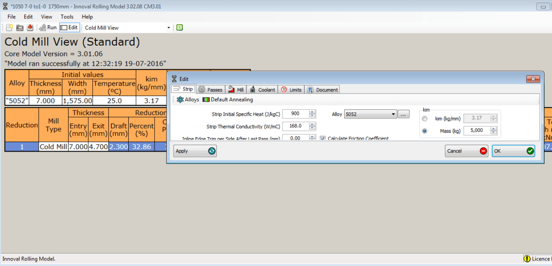
So, what happens when we roll AA5052? To find out we simply change the material we are rolling to match the new alloy, along with any special changes in the pass.
This generates the expected rolling conditions for our new material. The model shows that our expected rolling force is now 9115 kN. But what does this mean for the rolls?
The rolls in the mill are going to bend and deflect under load. The additional deformation will tend to over roll the edges of the material. This will make the material looser and create edge waves. We will need to compensate for the additional deformation by using a positive bend or by grinding a different camber on the rolls. We’ll now consider the latter of these two options.
Roll camber
With the aid of the Innoval Stack Deflection Model, we can investigate the change in shape of the roll. Using the geometric information of the mill and considering the crown being used, we can determine the change in the roll gap due to the change in load.
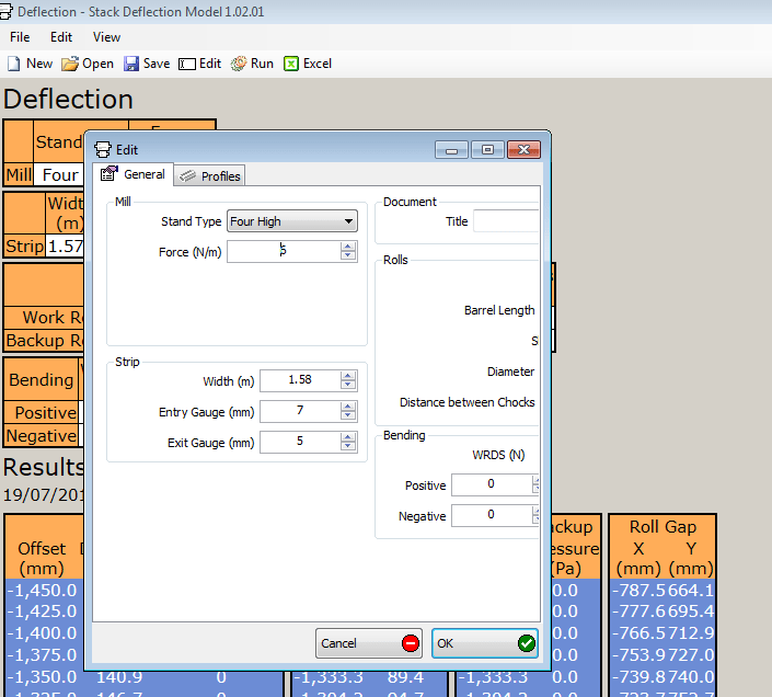
With the data from the modelled passes, we can determine the difference in expected deformation of the rolls. This will give us the expected amount of deflection that we need to compensate for.
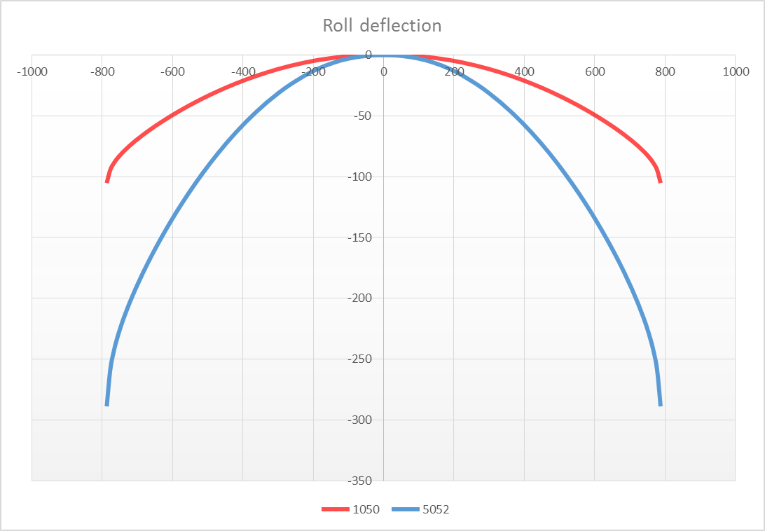
By employing aluminium rolling models such as these, we can predict the required camber of the rolls before the trial. As a result, our first time pass rate for the new product should be very high.
If you want to know more about our rolling model, you can watch a short animation here.