
Posted on: 22nd June 2021
The word ‘grain’ appears everywhere in aluminium metallurgy. How do we analyse aluminium alloy grains? Why do we want to look at them? I’ll answer these questions in this blog. However, first we need an aluminium metallurgy 101.
What is a grain?
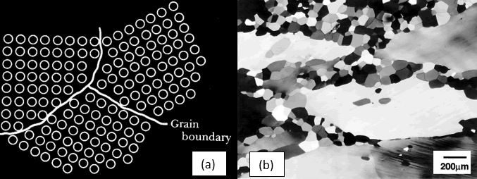
In the solid state, aluminium atoms occupy a face-centred cubic structure. During solidification regions, or ‘crystallites’, of solid aluminium start to form where the atoms are all aligned in the same orientation. These are called grains. As solidification progresses and these regions start to grow, the intersection between crystallites of different orientations form grain boundaries. Figure 1(a) and (b) illustrate aluminium alloy grains and grain boundaries.
The orientation of the grains in the microstructure is known as ‘texture’. When a large fraction of the grains in the microstructure orient in similar directions, the material has a strong texture. Conversely, with dissimilar orientations, the material has a weak or random texture.
Texture can develop during the manufacturing of the material. It can be an advantage or a disadvantage depending on the alloy and application. However, it can be quite a complex topic, with analytical techniques that are beyond what I will talk about in this blog.
Effect on material properties
Because grains make up the material structure, you can imagine that they play a key role in the material properties. For instance, the grain size and therefore density of grain boundaries, can help strengthen the material. This is captured in the Hall-Petch relationship in Equation 1.
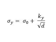
In the Hall-Petch equation, d is the average grain diameter, σy is the material yield stress, σ0 is a materials constant for the starting stress for dislocation movement and ky is the strengthening coefficient, a constant specific to the material.
The Hall-Petch relation shows how a decrease in grain diameter and therefore an increase in grain boundary area, helps to strengthen the material (increase in yield stress).
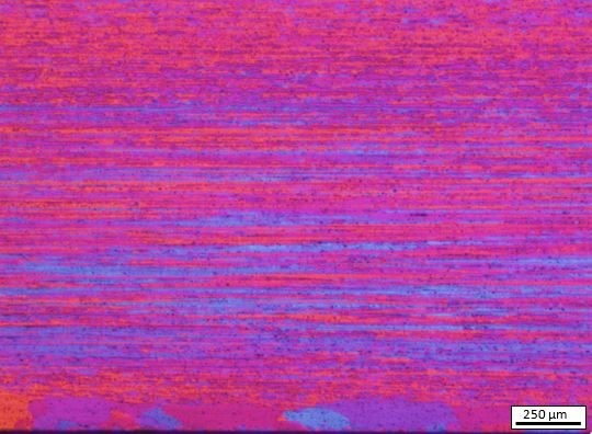
Grain manipulation occurs throughout the processing of aluminium alloys. It can happen in the initial solidification, through various heat treatments and via deformation during processing. One example of texture formation as a result of processing conditions is the Peripheral Coarse Grains (PCGs) that form during extrusion in the near surface region. Figure 2 shows an example of the larger PCGs in a cross-sectional micrograph of an extruded alloy. PCGs are one example of a microstructural defect that is detrimental to material properties.
An excellent textbook for everything to do with the deformation and heat treatment of grains is this one: Recrystallisation and Related Annealing Phenomena by F.J. Humphreys and M Hatherly. I highly recommend it to any metallurgist new to the aluminium industry.
How do we analyse aluminium alloy grains?
Before we can even think about viewing microstructure under a microscope, we need to consider what information we are trying to find. For example, if we are interested in the ‘texture’ of the material, we will typically need Electron BackScatter Detection (EBSD) utilising a FEG-SEM microscope. However, if we simply want to understand the grain size and general morphology, we can use etching techniques in combination with an optical microscope.
I will now explain the sample preparation and imaging techniques for optical microscopy. This is the most readily accessible and user-friendly technique of those I’ve mentioned above.
Polishing the sample
I have, over the years, learnt two key things when preparing metallic samples, patience and cleanliness.
If you rush sample preparation, you will ultimately end up with large unwanted scratches. If you do not take care with the cleanliness of the equipment and sample, you will contaminate the sample surface (most likely with crystallised colloidal silica suspension which can be a nightmare!).
General metallic sample preparation consists of grinding the sample with Silicon Carbide (SiC) paper. You would start with a coarser grade (like P320) and work through finer grades such as P600, P1200, P2500 and P4000. This sequential method makes sure you remove the deformation from previous steps.
Once you have ground your sample, there needs to be a final polishing step to create a mirror-like finish. For the final polishing you would typically use a colloidal silica suspension (OPS). Final cleaning of the sample immediately after the OPS polishing with either water, methanol or acetone is critical. This is because OPS dries quickly on the surface and becomes difficult to remove.
Etching the sample
If you prepare your aluminium alloy sample as I’ve described above, you will still not be able to see the grains. To make grains in different orientations stand out so you can see them, you need to ‘etch’ the sample. This works because the etching solution preferentially ‘attacks’ grains in certain orientations, thus making them visible.
Etching typically involves a range of acidic solutions and electrolytic techniques. Exactly what you’d use depends on the aluminium alloy composition, temper and designation. A few etchants that we typically use for aluminium alloys include Keller’s Reagent, Barker’s Reagent and Weck’s reagent.
Here at Innoval we commonly etch samples by electrolytic anodising in Barker’s Reagent. This method creates a conductive path across the aluminium sample (anode) to a cathode once a current is applied.
Optical microscopy
After you’ve polished and etched or anodised the sample, it will be ready to view under the microscope.
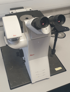
We have several optical microscopes at Innoval. However, the microscope we use for imaging grain structures is an inverted Leica DMi8 microscope. It is equipped with an adjustable polarising filter and quarter waveplate. You can see a picture of it in Figure 3.
Figures 4 and 5 below, which we prepared using Barker’s Reagent, show examples of what you can achieve with varying aluminium alloy series.
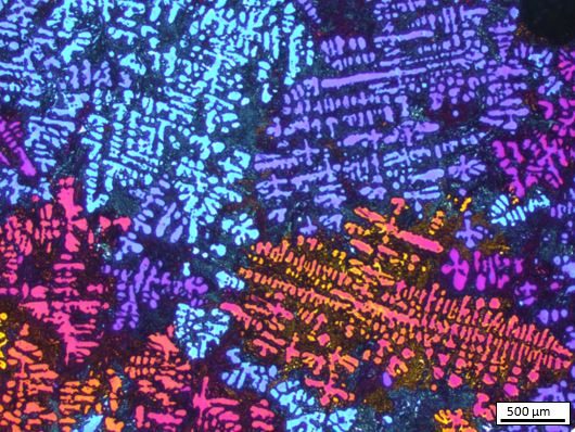
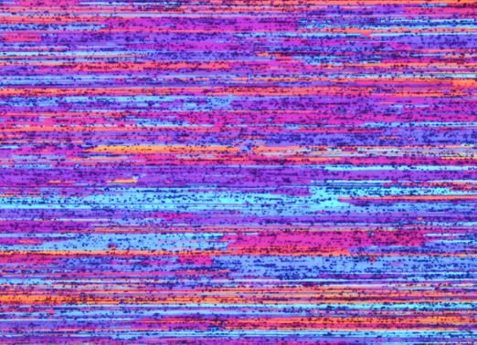
If you’d like to learn more about aluminium microstructure and how it affects product performance, please consider taking part in our ‘Introduction to Aluminium Metallurgy’ training course. This is an online course which takes place several times a year in three half-day sessions. You can find out more here.