
Posted on: 12th January 2018
In the previous blog I discussed some of the challenges of measuring fracture toughness in aluminium extrusions. In this post I will introduce some of the tests we do at Innoval, as well as describing one that we are developing.
The notch tensile test
The notch tensile test, as defined in ASTM E338, generates the notch yield ratio.
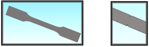
It involves machining a tensile sample with a double notch in the central gauge length region, figure 1. You then compare the peak stress from this sample with the yield stress values obtained from an un-notched normal test piece.
If the notch tensile value is above the yield stress, then the material can accommodate plastic deformation in the presence of a stress raiser. Conversely, if the notch tensile stress values are lower than the yield stress, than the material is unable to accommodate plastic deformation in the presence of a notch.
This comparative test allows you to rank different alloys and tempers against each other. However, as with all tests of this type, the crack tip geometry has a strong influence. In this test there must be a ‘sharp notch’. Studies show that a 60 deg notch angle provides the greatest discrimination.
The Kahn tear test
You can use the Kahn tear test, carried out to ASTM B871, for the relative ranking of fracture toughness in thin gauge products. However, the stress field around the notch varies with material thickness. Therefore, you should only make comparisons between similar gauges.
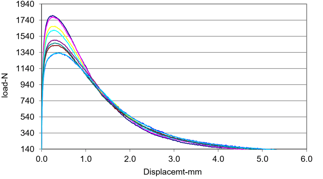
An example of some load displacement curves is shown in figure 2. It is possible to break down this data into two distinct regions. The area up to peak load is the crack initiation energy, or UIE (Unit Initiation Energy, KJm-2). The area post peak load, to the point of failure, is the propagation energy, or UPE (Unit propagation Energy, KJm-2). This is essentially the energy needed to propagate a crack, or the material’s ability to resist tearing.
With the Kahn tear test we assume that the crack will initiate at peak load. Once again, this makes the notch root radius a critical parameter. UIE is heavily dependent on notch geometry. As a result of this, the propagation energy is of greater importance.
Our improvements
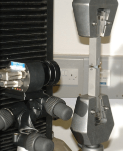
In conjunction with WMG at Warwick University, we’ve been able to significantly update and improve the basic Kahn tear test. We’ve designed grips for the test which give open access to the notch root and tear propagation path, figure 3.
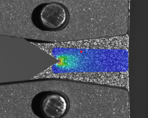
Used in conjunction with Aramis and GOM non-contact strain acquisition equipment, we measure strain where it actually occurs – at the notch root (figure 4). In this way, the results are not complicated by elastic strains within the load train. Neither are they complicated by plastic strains around the pin loading holes. We know that both of these introduce error to the test. Furthermore, our method does not require comparison with an un-notched sample.
In addition to the above, every test has a digital image record of the tear initiating and propagating through the sample. This provides valuable information on, for example, tear deviation which may be associated with extrusion defects.
Short rod fracture toughness testing
I’m now going to describe some work we’re doing at Innoval to improve the short rod fracture toughness test (ASTM E1304).
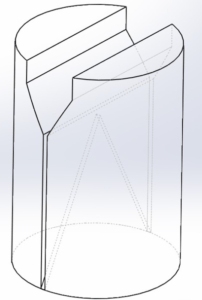
This test uses an innovative design of test specimen, figure 5. It consists of a chevron notch inside a cylinder of approximately ½” (1.27 cm) diameter. You can produce the test piece from conventional extrusions. However, machining the chevron notch requires precision tooling.
The test piece is easier to make than a standard fracture toughness sample for compact tension. Furthermore, the test is much quicker to do. This is because no pre-cracking is required to generate a defect, as would normally be the case. Instead, a slowly advancing crack initiates at the tip of the chevron notch when the ends of the sample are slowly driven apart within a stiff load frame, figure 6.
As with the Kahn tear test, we intend to use non-contact strain acquisition to monitor displacement on the sample. This will avoid compliance errors and expensive custom extensometry. The load displacement data is the same as with the Kahn tear test. However, at the point on the curve where it deviates from elastic deformation, we make an assumption that the crack initiates at the tip of the chevron. The specimen design makes crack growth stable. An increase in load is required to advance the crack further until a critical crack length is achieved at peak load. This then decays.
Previous evaluations of this technique in the early 1980’s show that it gives good correlation with conventional fracture toughness testing. Using non-contact stain acquisition equipment should enhance the accuracy further when evaluating the latest generation of aluminium alloys.