
Posted on: 17th March 2023
In this Insights article I’m going to give an example of how we use finite element analysis tools in our work for clients. In this case, our client wanted us to look at how changing the design of some AA6005a extrusions could increase the load carrying capacity of a structure. For us to do this, we needed to carry out a stress analysis.
I will cover some of the designs we explored to increase the load capacity whilst reducing the local stresses to below the softening factor stress. However, we also wanted to include an appropriate safety factor, or safe working limit. The Machinery’s Handbook provides safety factors for design engineers. For this structural application 1.5-2 was appropriate as we are using reliable materials and the environmental conditions were not severe.
The structure.
The structure consisted of three load bearing extrusions which you can see in Figure 1:
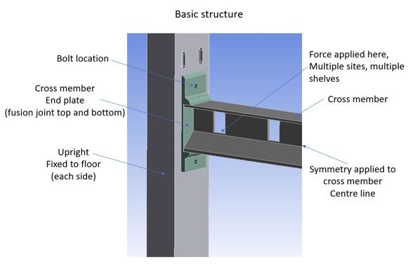
There were two vertical uprights bolted to the floor via a welded base plate. Multiple beams straddled the two uprights with bolts through welded end plates keeping them in place. All extrusions were in the T5 condition prior to fabrication.
Some background about structural alloys.
Generally, aluminium alloys fall into two categories. Heat treatable alloys can have their properties improved by one or more thermal treatments. On the other hand, non-heat treatable alloys have their properties improved by cold deformation and work hardening.
Structural medium strength extrusions are predominantly made from aluminium alloys that are easy to extrude. This is because they have an elevated temperature flow stress typically less than 20MPa. They are insensitive to corrosion and can be age hardened (heat treated) with comparative ease to raise their mechanical strength. The main alloying elements for this group of alloys are magnesium and silicon (AlMgSi0.7). However, the AA6005a alloy used for this application has additions of manganese and chromium to specifically improve toughness and crack resistance. As a result, it’s one of the main alloys used today for structural extruded profiles.
In addition to the mechanical properties mentioned earlier, AA6005a also offers excellent weldability using either 4000 or 5000 filler wire. However, when aluminium is fusion welded, metal from the individual part melts and re-solidifies as one piece. The region of metal adjacent to the re-solidified joint is exposed to the heat used in the melting process, creating a heat-affected zone. In this region, the temperature is high enough to cause changes in the alloy microstructure. These can significantly affect the mechanical properties of the metal, reducing the local strength by as much as 50%.
Softening factors.
To render these extruded alloys safe to use in welded structural applications BS EN-1999-1 “Design of Aluminium Structures-General Rules” defines specific softening factors which we must apply to the mechanical properties of the extruded section after we’ve created a fusion joint.
Although this document does not specifically refer to AA6005a-T5, it does reference several AlMgSi alloys. From the values applied to these other alloys it is fair to assume AA6005a-T5 would retain about 48% of its proof stress after welding.
AA6005a 0.2%PS 240 (MPa) x 0.48 = 115.2MPa.
This represents the limiting stress or onset of plasticity which we could expect in the heat-affected zone of a fusion joint if the local stress exceeds 115.2MPa.
Finite Element Analysis (FEA) tools for stress analysis.
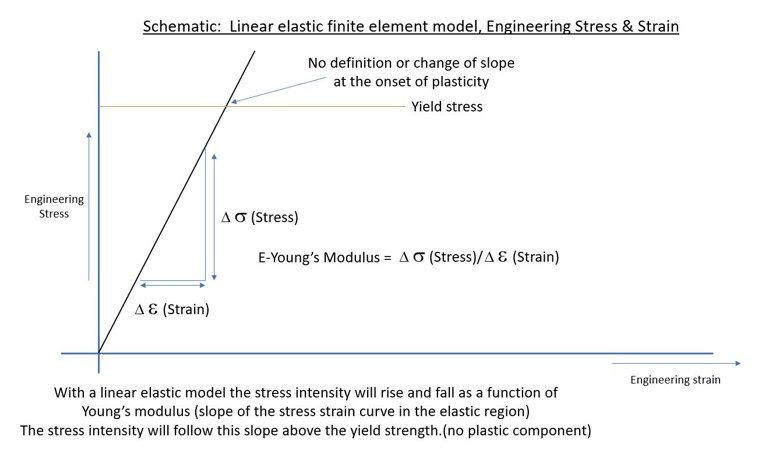
At Innoval the finite element analysis tools we use are Solidworks Premium and Ansys Mechanical Pro. Solidworks Premium has a linear elastic finite element solver which will determine induced stress within a model based on Young’s modulus. (Figure 2, elastic stiffness). This is 70GPa in our case. Stresses within this model take no account of yield, the onset of plasticity or any associated work hardening that may take place. However, it is suitable for analysis where stresses fall below the yield strength.
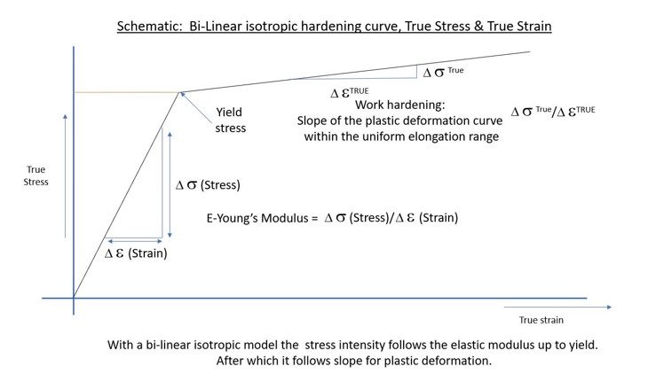
Ansys Mechanical Pro has an FEA solver that follows a bi-linear isotropic hardening curve based on uni-axial mechanical data from real tests (Figure 3). This solver follows the true deformation characteristics of the material. Hence, it is the generally accepted method for simulating the plastic deformation of aluminium. We define the rate of change of work hardening by the slope of the true stress, true strain curve within the uniform elongation range. The definition of this range is “post yield up to the onset of necking”. Ansys defines this region as tangent modulus or slope of the curve post yield.
Model development strategy.
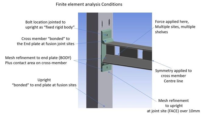
At Innoval we model the parts typically mid tolerance and build the assembly models within Solidworks. We migrate the files into Ansys as IGES files and we add the appropriate connections, boundary conditions and forces to the structure. For this model the cross members were “bonded” to the end plates where they would actually be welded together (not all the contact faces). However, a “bonded” boundary condition will behave as if welded. We also applied a symmetry condition to the centre line of the cross member to save computation time (Figure 4).
Mesh details.
The FEA set-up will also include mesh refinement within the cross-member end plates (body). It also includes face refinement around the location slots in the uprights to provide greater accuracy within the critical areas (Figure 5).
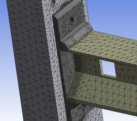
For additional accuracy, we’ve used quadratic tetrahedral elements. A quadratic element has a node in the middle of each side of the element. This additional node allows the element to form a curve between the 3 nodes. This in turn allows the elements to follow the deformed geometry more accurately. However, it does add computational time. Finally, we have not carried out any simplification of the models. We modeled the extruded profiles according to the die drawings.
Outcome.
The individual extruded profiles went through multiple iterations to achieve the final required load state. Using Ansys and Solidworks enabled us to alter the assembly model. We created a new version, then migrated the IGES file into Ansys, updating the geometry and improving set-up time.
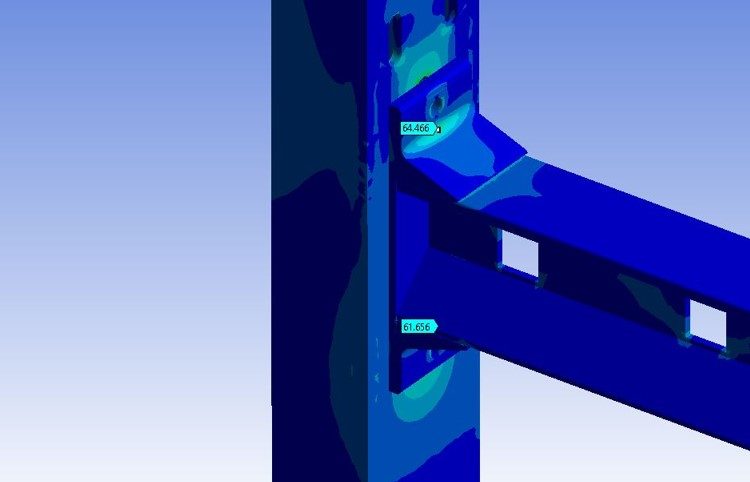
During this analysis weight was a major consideration, not only for the cost/m of the extrusions, but also for shipping costs as well. For the final version (Figure 6) some parts went through 34 iterations to optimise their design! Typically, the weight/m increased by 20-30%. However, the loading capacity also increased by 30%. Deflections within the cross beam were down, and all welded parts complied with the imposed softening factors. Figure 6 shows the peak stresses in the welded end plate to be 64.5MPa. The softening factor 115.2/64.5 gives a safety factor of 1.78, which complies with Machinery’s Handbook.
How we can help.
Innoval has a range of engineering design and simulation tools available to help optimise aluminium component and system geometries. Stress analysis, as demonstrated here, is just one part of this.
Analyses such as these can lead to more efficient, safer and more sustainable products while reducing expensive prototyping stages. Please get in touch with us to find out how we might be able to support your next product development project.