
Posted on: 16th November 2016
In my last blog post I described some common mill vibration problems, including third octave gauge chatter. This week I will concentrate on fifth octave chatter and chatter marks.
Third octave gauge chatter and fifth octave chatter are two common forms of mill vibration that are difficult to solve. Both can cause significant strip quality issues if they occur on a mill. There is always a source of vibration responsible for fifth octave chatter, which causes chatter marks on the strip. Consequently, a solution can usually be found to this type of problem.
Sources of chatter marks
Fifth octave chatter marks usually develop on the backup roll barrel. The chatter marks print via the work roll onto the strip surface with a spacing of between 10 and 40mm.
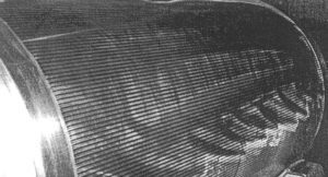
Figure 1 shows an example of severe chatter marks around the barrel of a backup roll before grinding. The markings are parallel to the roll axis and often have uniform intensity across the backup roll barrel. With very sensitive surface proximity measurements it is possible to measure surface features with amplitude of a few microns that relate to the markings.
The chatter mark problem requires a source of forced vibration within the mill. Typical sources on the mill may be forced vibrations from defective gear teeth, roll bearings and drive couplings. If the forced vibration excites a fifth octave resonance of the mill stand, then the flexibility of the mill will increase the vibration amplitude. This will make the marking problem more severe. The vibration frequency associated with fifth octave chatter is usually in the range 600 to 1200Hz.
Another source of forced vibration in the mill is due to periodic sub-micron features on the roll surface produced during roll grinding. Forced vibrations create these features within the roll grinder. They usually also excite a natural resonance of the grinding machine. Very careful vibration measurements are required to identify the source of the marking before this problem can be solved.
Computer simulation of mill vibration
It is usually helpful to understand the fifth octave resonant frequencies of the mill stand. Computer simulation or experimental modal analysis are two approaches. If the grinder is involved then a full modal analysis of the grinder is also useful.

Figure 2 shows a typical fifth octave chatter mode that can be responsible for producing chatter marks if excited in a 4-high mill. The mode involves the two work rolls moving in-phase and vibrating between the two backup rolls. The backup rolls move in anti-phase to the work rolls, but their amplitude is significantly less than the work roll amplitude.
The relative motion between the work roll and the backup roll damages the backup roll surface during the period that the backup roll is in the mill. Furthermore, the predicted mode involves significant bending of the work roll necks. This type of mode belongs to a family of fifth octave modes. All can damage the backup roll through the relative motion between the work roll and backup roll.
Some solutions to this problem may require an on-line monitoring strategy on the grinder and/or the mill to identify the source and then minimise its impact. This is an effective operational strategy to maximise productivity while maintaining a high quality strip surface.
Innoval has a lot of experience in solving mill vibration issues. One of the tools we use is the Innoval Mill Vibration Model which is a finite element-based model. Please contact us if you’d like to know more.
This blog post was originally written by Dr Tom Farley who has now left the company. Please contact Kyle Smith if you have any questions.