
Posted on: 5th July 2023
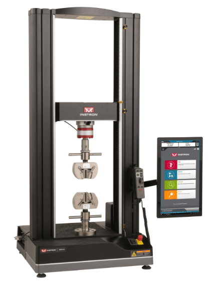
We’ve recently added a new 50kN load frame from Instron to our mechanical testing equipment. This allows us to conduct all the usual tensile test parameters such as strength and ductility. However, in addition, we’re also able to perform more specialised tests such as fracture toughness, bend testing and crush testing.
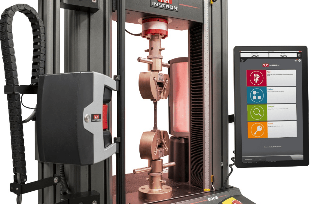
Our new load frame has a fully integrated high-resolution non-contacting video extensometer. This gives us the capability to measure strain on numerous samples from automotive sheet down to thin foil gauges. We are also able to determine proof stress which is the point when the material starts to undergo permanent plastic deformation (more on that later). Furthermore, the extensometer is fully compliant with all relevant metal test standards.
In this Insights post I am going to explain how we measure some of these basic properties in aluminium. To start with, I’ll discuss engineering stress and strain and room temperature static uni-axial mechanical properties. In a later post I will cover true stress and true strain.
Why perform a tensile test?
We all have a feeling about how strong something is. Every day we encounter different materials; wood, plastic, glass, steel, aluminium, carbon fibre, and rubber to name a few. These materials are all around us in the products we take for granted in our everyday lives. The fact that we use them safely and reliably is down to careful materials selection and good engineering design. When designing a product, we need to know the strength of the material we are going to use to make it. But we also need to understand its end use. Although, thankfully, material failures are rare occurrences in the real world, there have been some historical cases that have taught us a great deal about how we use material properties and design products.
Let’s consider failure mechanisms.
The Tay Bridge

In the Tay Bridge disaster in 1879, the iron railway bridge collapsed as a train crossed it during a storm.
At the time, investigators concluded that the bridge designers had underestimated the wind load. So, in this case, it was the environmental conditions, and not the mechanical properties of the material which caused the problem. However, in recent times, thanks to a digital microscope, this view has changed. Engineers now believe the fault lies with the use of cast iron for the lugs. You can read the full story here.
Liberty Ships
In another example, the famous Liberty Ships from the second world war were found to have failed due to brittle facture of the welded hull. This was not because engineers didn’t know the parent material strength. It was because the joining technique resulted in low notch toughness adjacent to the weld, forming cracks that could travel huge distances.
De-Havilland Comets
The loss of two De-Havilland Comets (the first jet airliner) was not down to strength of the aluminium used in construction of the fuselage. In fact, the minimum safety factors were surpassed. The failures happened due to the design of the windows, which led to stress concentrations and failure from fatigue.
These examples illustrate that, while it’s critical to understand the strength of our starting materials, it does not always mean we can design something that will be safe for the entirety of its life without encountering problems. Strength defines the maximum stress a material can withstand, but failure can occur from many mechanisms, including fatigue, environmental corrosion, brittle fracture, thermal effects and poor design in general.
Today we can test a material and use the actual yield strength, elastic/plastic stiffness, tensile strength and ductility values to create a ‘material card’. We can then use this to carry out sophisticated engineering calculations using finite element analysis (FEA) to verify that our design is fit for purpose.
The static-uniaxial tensile test (strength) in metals.
To begin with, I’d like to clarify a couple of things. Firstly, ‘static’ means the material experiences slow and constant loading. In this case, the test speed is less than 2mm/min. Secondly, ‘uni-axial’ defines the load path which, in this case, is in one direction. The typical output is an engineering stress-strain curve, as shown in Figure 4.
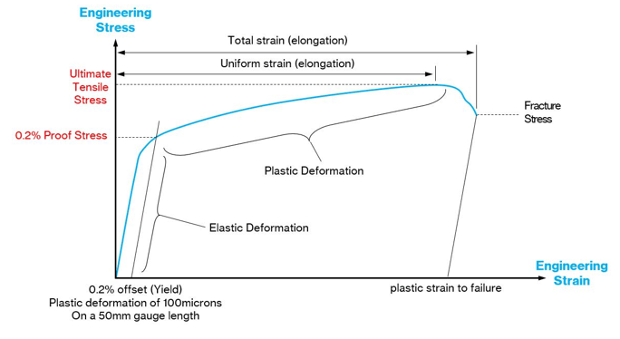
Now let me introduce Ultimate Tensile Strength.
Ultimate tensile strength (UTS) = Peak load from tensile test (N) / Original cross-sectional area (mm2 )
We also call UTS ‘maximum engineering stress’ and it is measured in N/mm2 or MPa. However, the lessons from history show us that if we design something based on ultimate tensile strength alone then there is a risk our products could fail! We therefore need additional parameters for design engineers to use that enable us to create safe, fit-for-purpose products that are not so heavily over engineered that they incur needless expense and waste. We can obtain many other useful parameters from the uniaxial tensile test, as I will explain below.
A word on stiffness.
At this point we need to step back from the tensile test to discuss stiffness. The stiffness of a material (not a part or component) is an intrinsic material property unique to that material. Stiffness is the ability of a material to resist elastic deformation, figure 5. A material that has a greater change in stress with respect to strain compared to another material will be stiffer. Elastic deformations in metals are small (microns) and require precise instrumentation to measure accurately. These instruments are called extensometers. They have defined lengths, for example 50mm, over which they record strain to comply with relevant standards.
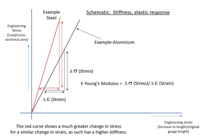
Typically, the stiffness or modulus of elasticity, is quoted in gigapascals, GPa. It defines the elastic properties or elastic response.
The Young’s modulus (E) is a property of a material that tells us how easily it can stretch and deform. It is defined as the ratio of tensile stress (σ) to tensile strain (ε). Where stress is the amount of force applied per unit area (σ = F/A) and strain is extension per unit length (ε = dl/l).
Aluminium has a Youngs Modulus of approximately 70GPa. For steel it is 210GPa, meaning it is 3 times stiffer than aluminium.
To provide a safe level of stress that engineers can comfortably use, we define a stress based on the modulus (elastic slope). For aluminium the value of stress is commonly known as an ‘offset yield’ or 0.2% proof stress, as depicted in Figure 4. This means we apply 0.2% plastic strain to our test piece over a defined region within the reduced section or gauge length (see final section about test piece geometry).
Example:
Our sample defined region is 50mm = 0.2/100*50 = 0.10mm or 100 microns.
If we project a line offset by 100 microns parallel with the modulus, where this line intercepts the load displacement curve, we record the load. We can then use this to calculate the proof stress based on the original sample dimensions, Figure 4.
0.2% offset yield (proof stress) = Load (from intercept) (N) / Original cross-section area (mm2 )
We measure the 0.2% proof stress in N/mm2 or MPa.
In summary, all we are doing is imposing a small plastic deformation of 100 microns and recording the load required to do this. From this we calculate the stress, which design engineers can then use for a safe in-service stress or load state.
The tensile test piece geometry.
To carry out a tensile test we need to use an accurately machined sample. Figure 6 is an example of an Innoval test piece. The test piece has a reduced section or gauge length. This focusses the strain and allows us to measure it accurately with our video extensometer within this one region. We call the reduced section the test piece gauge length. The video extensometer will have a smaller gauge length (typically 50mm) and will measure strain centrally within this region.
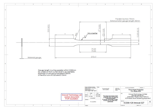
There are many different shapes and sizes of test piece and I will discuss their use in another post about automotive extrusions and sheet.
If you’d like to find out more about Innoval’s materials testing services, please visit this page and send us a message.