
Posted on: 12th May 2017
Aluminium is the preferred material for both engine cooling and air conditioning in cars. This is due to its unique combination of strength, corrosion resistance and recyclability. Of course, it plays an important part in vehicle lightweighting too. As a result, there have been numerous developments in the aluminium brazing process, the flux chemistry and in system design to make its use more cost-effective.
The need for aluminium brazing simulation
Controlled atmosphere brazing (CAB) is the primary process for manufacturing aluminium heat exchangers. Consequently it is undergoing continuous development to meet the challenges of today’s OEM’s.
The CAB process requires accurate control of the thermal cycle from room temperature to >600°C in an inert gas atmosphere. However, the continuous industrial CAB furnaces are not suitable for running trials to optimise the process conditions for new materials and designs.
Innoval does a lot of work for aluminium heat exchanger manufacturers and their suppliers. This is either an R&D project or an investigation to get to the bottom of a production problem. To do this we’ve developed several techniques to establish the surface condition of sheet products. For clad products, oxide film thickness and carbon residue are two key factors in brazeability. We are able to measure both of these using our FTIR and Leco carbon analyser. However, we have found that relating these to brazing performance with a practical method is crucial to understanding the balancing act between oxide, carbon and flux levels.
After reviewing all ‘off-the-shelf’ options for an aluminium brazing furnace suitable for experiments in the lab, we decided to manufacture our own, Figure 1. We wanted a glass tube furnace that would meet our experimental needs for characterising and testing brazeability.
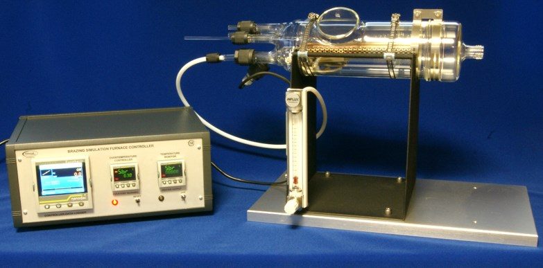
Innoval’s table-top aluminium brazing furnace
Our brazing furnace bridges the gap between the theoretical brazeability based on oxide and carbon results, and industrial trials. We can program it to run an almost infinite number of braze profiles in an inert gas environment. Typically we use nitrogen gas with certified levels of oxygen as a contaminant. We can also use it to assess the impact of metallurgical properties like microstructure and grain structure on the brazing process. We do this using a simple angle-on-coupon test specimen.
It’s also possible to evaluate other material parameters such as the cladding alloy chemistry, clad ratio and surface condition of the clad alloy, together with flux type and flux load.
The tube furnace has a viewing window for in-situ video monitoring of the clad melting and fillet formation process. This provides a valuable insight into the critical events which occur during the brazing cycle.
The test pieces
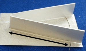
During brazing we use an angle-on-coupon (AoC) test piece as a standard, Figure 3.
This consists of a clad product as the coupon and a 3003 alloy for the angle, which represents the tube and fin found in heat exchangers. These are, of course, customer dependant and we can vary both.
The coupon is usually coated with flux. We raise the angle with stainless steel wire to make it harder to form a complete fillet.
An example of how we use our furnace
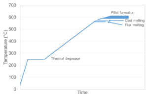
During brazing, the balancing act between time and temperature is critical to achieving a good brazed product, assuming the surface chemistry is favourable. For example, it may seem possible to reduce the number of rejects by using a longer dwell time at the peak temperature of the braze cycle.
The example in Figure 4 shows two identical AoC samples of a tubestock prepared with the same flux load. Both experienced the same temperatures during a braze cycle. However, the sample on the right had an extended dwell time at peak temperature. This has resulted in severe erosion of the core alloy of the tubestock, and has eroded a great deal of the 3003 angle.
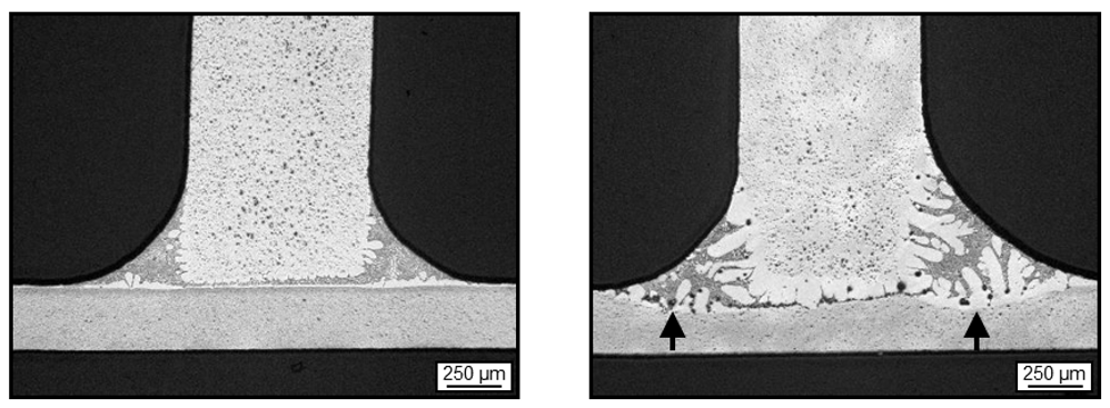
If the over brazing shown here had occurred on a heat exchanger, the manufacturer could expect to see a significant reduction in the strength of the tubes due to the reduction in the cross sectional area. There could also be a reduction in corrosion resistance depending on the alloys used.
The image on the left shows a good uniform brown band* region which is typical of long life alloys. However, the image on the right has no perceptible brown band formation, and would therefore have decreased resistance to corrosion.
*The ‘brown band’ forms during brazing. It consists of densely precipitated particles containing Al, Mn and Si. This band is typically a few tens of microns thick at the surface of the core adjacent to the cladding layer. The brown band is responsible for corrosion resistance of the clad side of the brazed product.
Optimise your aluminium brazing process
Do you want to optimise your CAB process without incurring downtime? Are you curious to know if you could get more out of your CAB furnace without compromising the product? We can help you answer these questions using our lab-based aluminium brazing furnace.
If you’d like to find out how we can help you or you have any questions regarding our brazeability testing, please contact us.