
Posted on: 17th May 2018
Flatness measurement and control has improved over recent years to the extent that the central part of the strip generally conforms well to the target flatness curve. However, there are still problems in controlling the strip edge.
One reason is the ability to measure the strip flatness accurately across the strip width. This is what I’m going to briefly discuss in this blog.
Why the strip edge is a problem
Problems in controlling the strip edge persist because the strain differences within the strip are most marked at the edge. This is where many mechanical and thermal parameters exert a strong influence.
A thermal gradient in the work roll exists across the strip boundary. This is because of the conduction of heat axially from the part of the roll in contact with the strip and the cooler parts of the roll which have not received the heat flows from deformation and friction.
Mechanically, there is the impact of roll flattening and the change in boundary condition at the strip. Plane strain conditions exist within the roll bite across the strip except at the edge. Here it changes to plane stress as the edge is free to move a little.
The main challenge
Given the stresses in the strip, can we actually measure the stress distribution correctly and so implement a good robust control scheme? Without good measurement, good control is problematic!
The earliest commercially available flatness measurement rolls had zone widths of 75 or 100 mm (3 or 4 “). The figures below include the modelled stress distribution for thin gauge product rolled at high speed and moderately large reduction. They show the influence on the measurements obtained for measurement rolls having sensors of different widths.
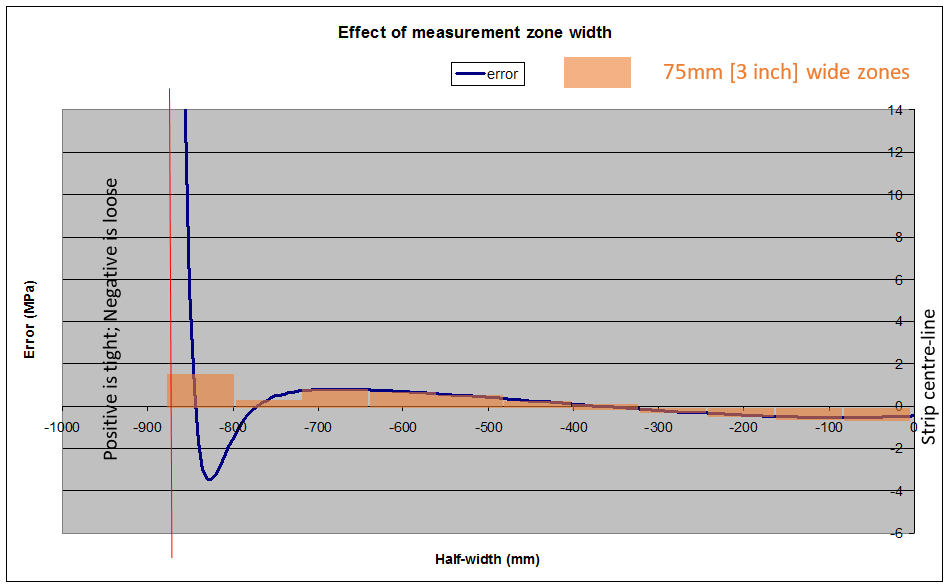
With the system in Figure 2 it would be impossible to tell from the flatness roll measurements shown in orange (which of course average signals over their zone width) that there is a problem at the strip edge. Note that in this example the strip edge is coincident with the edge of the measurement zone. However, this is something which does not happen that often in most rolling mill coil schedules.
Reducing the width of the measurement zone
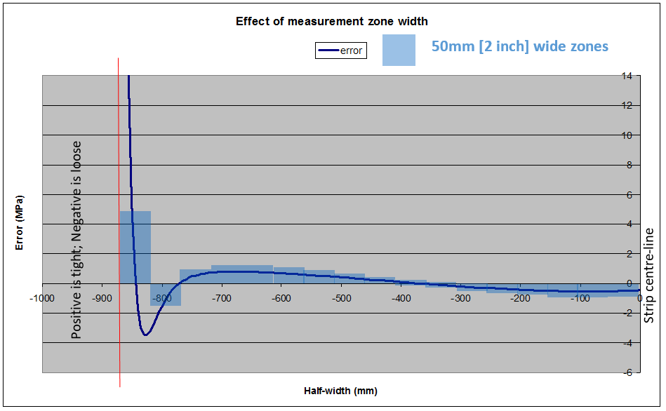
If we reduce the width of the measurement zone to 50 mm (2 “) then, clearly, the measurement roll will give a better picture of the real strip flatness. This is illustrated in Figure 3 below.
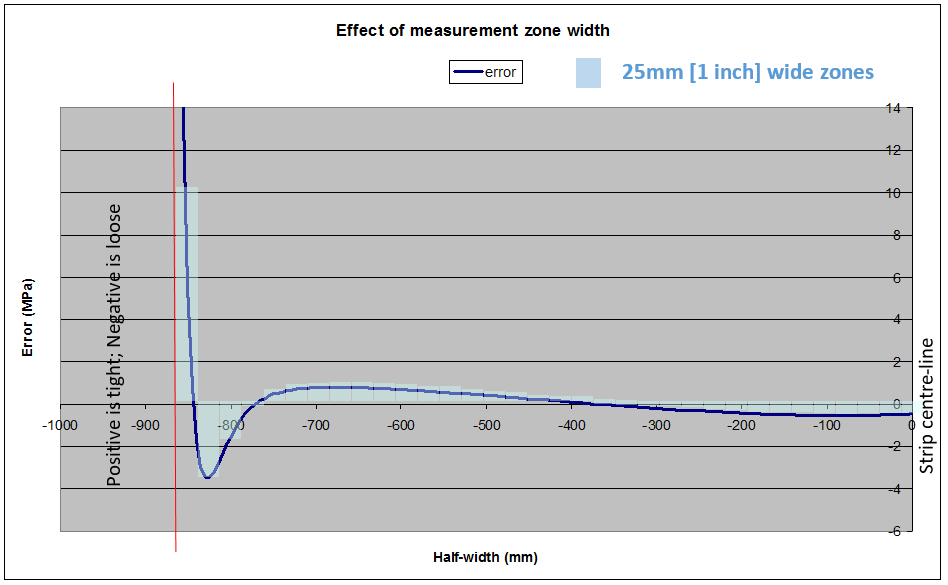
If we further reduce the width of the measurement zones to 25 mm (1″), then the data values presented to the control system reflect reality reasonably well. We can see this is the chart below.
Unfortunately, going to an even narrower measurement zone width is not commercially available. Of course it would be great to have more detail as to what exactly is happening at the edge!
Developing narrower sensors is partly technical, but the cost of a measurement roll is proportional to the number of channels measured. Because currently the smallest practical spacing for one key actuator (the coolant applied to the roll work surface) is 25 mm (1 “), we can’t expect to see a finer resolution commercial measurement roll in the near future.
More about flatness measurement
Our Aluminium Rolling Technology Course has several sessions on strip flatness, including ‘Mechanics of Profile & Flatness’ and ‘Automatic Flatness Control’.
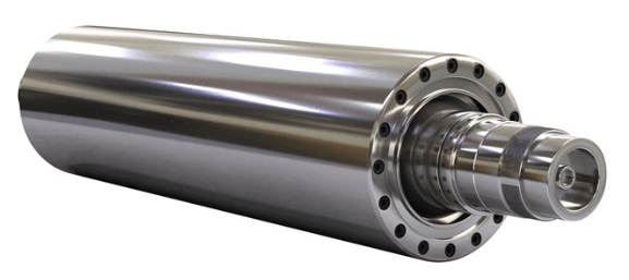
Figure 1 reference: https://www.materials.sandvik/en/products/hot-isostatic-pressed-hip-products/hip-product-examples/stressometers
This blog post was originally written by Dan Miller who has now left the company. Please contact Mark Rix if you have any questions.