
Posted on: 8th June 2017
The aluminium surface is very important. What goes on there can impact upon future performance, such as bond durability, corrosion resistance, paint / lacquer adhesion to mention but a few. In this blog I’ll describe how we use ultramicrotomy with transmission electron microscopy (TEM) to really understand the aluminium surface.
Why do we need understand the aluminium surface?
There are many questions involving the aluminium surface which we need to answer if we want our product to perform as it should. Is the surface clean? This means there are no disturbed layers. A disturbed layer incorporates residual oxides and metal from thermo-mechanical processing. Is the pretreatment the correct thickness and of uniform coverage? Is there even a pretreatment present?!
Unlike the more macro surface issues such as dents, scratches and metal cracking, the ones above occur on the micro / sub micro scale. Because of this, we often choose ultramicrotomy with transmission electron microscopy (TEM) as a means of analysis.
Ultramicrotomy
Ultramicrotomy is a technique involving cross-sectionaly ‘slicing’ very thin (~100nm, so it is electron transparent) sections with a diamond knife from an interface. As a result, the sections should incorporate bulk metal, surface oxides or pretreatment, and possibly an overlayer of lacquer or paint.
The slices produced are not only thin but their dimensions rarely exceed 1500 x 500 µm. Consequently, handling can be quite difficult.
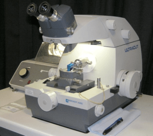
Figure 1 shows an ultramicrotome.
Sample preparation
You can see the process steps we go through to create a slice for TEM observation from a bulk metal sample in Figure 2.
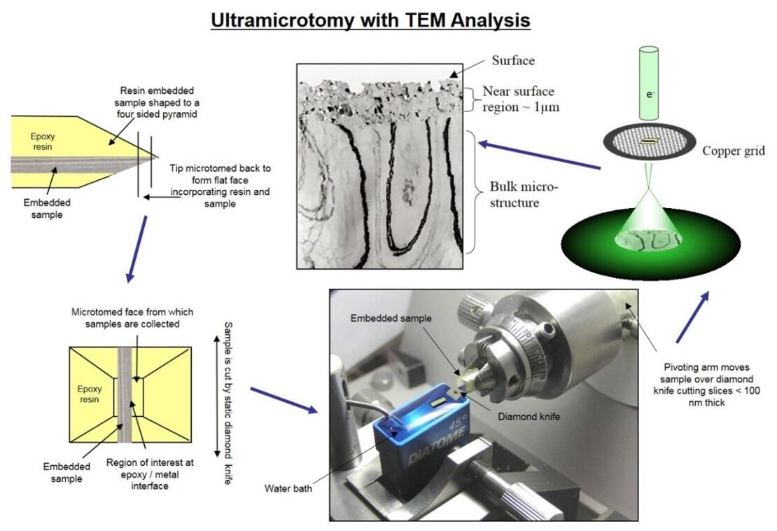
First of all we remove a small sample (~ 3 x 9 mm max) from the bulk material, generally with a jeweller’s saw. We sputter it with a very fine gold layer which helps define the outermost surface and aids focussing. We then mount the sample in a two part epoxy resin. This offers rigidity to the sample and enables us to section material as thin as foils. After this, we produce the samples as described in Figure 2.
We use a 3mm diameter copper grid to collect the slices from the water. It’s possible to capture up to 50 slices on the grid. As a result, we should uncover an ideal interface section. We then place the grid in the TEM for observation.
Ultramicrotomy is a technique I have been practising for around 30 years. I was told it was a science when I first started, but I quickly found it’s a bit of a ‘dark art’. Repeating the same method doesn’t always result in usable samples. In addition to cutting speed, water meniscus level and cutting thickness, air temperature and humidity also play a part in how well a sample will cut. Some days nothing works, so you just have to go home and try again the next day!
Some examples of what we can see
The images shown below are typical of the type of interfaces we monitor.
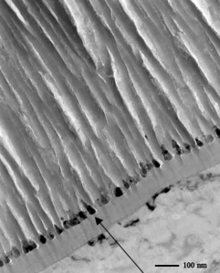
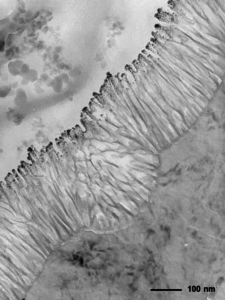
Figure 3 shows a thick porous anodic film with nickel deposits down the pores (adjacent to the barrier layer).
Light reflections cause, in this instance, the material to have a grey finish. The thickness and uniformity of the deposited nickel is critical to the colour.
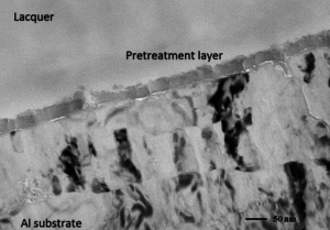
Figure 4 shows a typical chrome phosphate pretreatment film. It displays a uniform 30 nm thickness with continuous coverage.
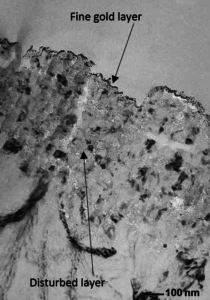
When a surface isn’t cleaned properly it can leave disturbed layers (Figure 5) consisting of rolled in oxides, fine grains and lubricants. This type of surface is quite reactive and is therefore a poor recipient of pretreatments or films.
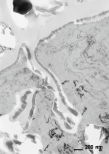
Partial cleaning can open up a surface resulting in voids and cracks. As Figure 6 shows, a pretreatment film can penetrate down into the surface.
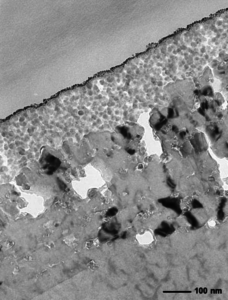
Figure 7 shows a thick Si based pretreatment film on a poorly cleaned surface. In this case, subsequent adhesion and durability may be a problem.
When everything goes right with the processing and sample preparation, it’s possible to obtain an image such as the one in Figure 8.
It shows a clean surface and a good anodic film with a fine layer of sputtered gold attached to the bonding media.
Invaluable observations
Over the years we’ve found these types of observations to be invaluable. As well as allowing us to monitor coatings, they also give us a deeper understanding of the interface and why it might fail. Furthermore, most TEMs are equipped with an EDX (energy dispersive x-ray analysis) facility offering elemental identification. Understanding where certain elements end up in and around an interface can really add to the story.
Whilst the technique requires a lot of patience and can be very frustrating at times, the results are often extremely rewarding. Here at Innoval we have several people who are now accomplished in the dark arts should you need an examination of an interface.
Over the years we have been involved with monitoring pretreatments and surface quality for many industries. Products have included automotive aluminium, internal and external architectural panels, food and drink containers and packaging, and various anodised products. In fact, just about anything involving an aluminium surface!
You can find more information about what we do here. Finally, if you’d like to read a brief overview of aluminium pretreatments, have a look at this blog.
This blog post was originally written by Pete Andrews who has now left the company. Please contact Dr Junjie Wang if you have any questions.